Motivations
For the last project in ARCH653, under the direction of Dr. Wei Yan at Texas A&M University, I decided to create a model that determines sightlines for theater design, concert hall, auditoriums, etc. This is a tedious and time consuming technical aspect of architectural design when made manually, but that can be automated for analysis of different design alternatives of a building, like a cinema complex. The "isacoustic" curve was developed by John Scott Russell in 1836, and my attempt is to automate the curve in Revit. There are many variations in sizes and distances according to the standards (distance from seats, distance from focal point, etc), but I chose some arbitrary standard units and started from there. However, those units can later be changed for different standards or purposes.
Model
Initially, I created a generic model mass family for each step (“step.rfa”) with an assigned “n” (instance parameter), which will be used later to assign a horizontal position in the project. That position will condition the height of the step to provide a proper sightline. The approach is to create parameters that can be easily assigned to a Revit model, leaving the complex parameters to be calculated by Revit API. In addition, I imported a theater seat and created parameters for an array arrangement based upon the width of the row.
 |
Figure 1: Parameters in the generic model family in Revit. |
To assign the horizontal position for “n” step, we used a “stage distance” (SD), in conjunction with a “focalheight” that determines the position of the most critical focal point. Then, I assigned a “Length” distance based on the “n” serial number multiplied by the constant separation between seats (n* T), where T = 3’6”). The “x” dimension includes the total distance from the focal point, represented by “SD + Length”. Finally, I created a parameter called “C”, which is basically the total height of the person seated minus the focalheight variable. This parameter will be linked later to calculate the vertical position of each seat using trigonometry in Revit API. I also added a “chair_v_d” parameter (stands for chair vertical distance) to control the distance of the seat to the top of the mass family (C parameter), taking as a reference the flat surface of the arm rest. I understand that the seats in a cinema will share the arm rest with their adjacent seats, but to simplify this project I will use a simpler arrangement.
 |
| Figure 2: Formulas for each parameter in the generic model family. |
To find out the exact formulas, I made a diagram of the manual calculation to find out the formulas:
where n denotes the serial number; C is the parameter to be calculated in Revit API; A is one angle of the triangle formed by the focal point (also calculated in Revit API), seat distance and the eye level of each spectator; SD is the Stage distance (known value); and T is the Thread (constant value of 3’6”). From this formula we can derive:
Atan (An) = C* (n-1) + 4” / SD + T (n-2);
Cn = Tan (An)* SD * (T * (n-1));
 |
| Figure 3: Concept drawing to explain the trigonometric formulas used. |
Then I created another generic model mass family (Project2.rfa) where I uploaded several “step.rfa” instances, all of them in the same location, selected one instance at a time and changed the "n" serial number in a consecutive order (1, 2, 3...etc). According to their serial “n”, each instance will move to the expected horizontal position. This family only incorporated the type parameters “StageDistance” and “focalheight” to be used later in the Revit API.
 |
| Figure 4: Project2.rfa parameters. |
Revit API
For writing Revit API codes, I used a template created and provided by Dr. Yan in class, using Microsoft Visual Studio 2008. First, I needed to identify the ID’s of each step used in Project2.rfa. For this, I selected them all, went to Manage in Revit, and clicked “ID’s of Selection”. Then I selected the numbers, copy (CTRL+C) and paste them in my VisualStudio code lines (you can see the comments in green in the API code). For this project, I created 6 instances of steps, so I have a total of 6 ID’s to include. The second step was to verify that the ID’s are consecutive numbers. To achieve this, I selected each instance in Revit, checked their “n” value, checked their ID number and re-located the ID’s in API to be consistent with the order of “n”.
The next step was to assign a FamilyManager value for “focalheight”, since I will use this to determine the location of the first C value.
Then I created a loop function to calculate each step’s vertical position, since each new position depends on the position of the seat right in front of it (for (int n = 1; n < 6; n++). Notice that we don’t need to calculate the first seat position, but we need to start calculating the position of the second row until the last “n”. In Revit API, the first of an array or series has an n=0 for the first instance, so our second row will have an n=1 value. ”n<6” means that we will calculate up to the 6th row, and n++ means that we will increment “n” by 1 for each consecutive step or row.
 |
| Figure 5: Revit API initial lines of codes. |
For getting objects in Revit API, we must refer to the Project2.rfa in order to input the values we need. If you recall, we are using Revit API to calculate what cannot be done in Revit Architecture, so we will only get the parameters needed for complex calculations. We need to separate the instance parameters from the type parameters, so as C is a parameter that has individual values according to the “n” associated with the instance step, it is considered as an Instance Parameter. Stage distance is a constant value for all the different rows, as well as the Thread parameter (constant value of 3’ 6”), so they are considered under type parameters.
Finally, we need to calculate the new C for each row, so we call math calculation formulas in API:
double An = Math.Atan((C[n - 1] + 4) / (StageDistanceParam.AsDouble() + ThreadParam.AsDouble() * (n - 2)));
C[n] = Math.Tan(An) * ((StageDistanceParam.AsDouble() + ThreadParam.AsDouble() * (n-1)));
And then we need to set C parameter values to re-locate each row in their expected vertical position. For this, we set the CParam according to each respective “n” value, and finish the loop here.
CParam.Set(C[n]);
 |
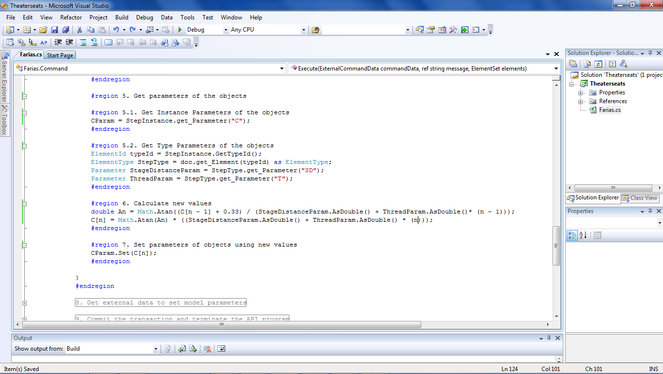
Figure 6: Revit API codes for writing formulas. |
 |
Figure 7: Wrong calculation in vertical distance. |
However, after measuring the distance between the steps, I found obvious errors. The vertical distance between each row should increase when “n” increases, but the opposite was occurring. Also, the vertical distance between rows was too high, which means that somehow the formula was incorrect.
double An = Math.Atan((C[n - 1] + 4) / (StageDistanceParam.AsDouble() + ThreadParam.AsDouble() * (n - 2)));
C[n] = Math.Tan(An) * ((StageDistanceParam.AsDouble() + ThreadParam.AsDouble() * (n-1)));
Since the original C in the diagram was calculated using the eye level and the additional 4” between the eye level and the top of the head; however, those 4” have to be converted into feet units (0.33’).
double An = Math.Atan((C[n - 1] + 0.33) / (StageDistanceParam.AsDouble() + ThreadParam.AsDouble() * (n - 2)));
C[n] = Math.Tan(An) * ((StageDistanceParam.AsDouble() + ThreadParam.AsDouble() * (n-1)));
 |
Figure 8: Revit API "Get Objects", "Parameters" and “Calculate new values”. |
That change led to better results calculating the vertical distance, but the progression in the vertical distance with increments of “n” was still backwards.
 |
Figure 9: Changes in our Project2.rfa after using our Add-ins from Revit API. |
 |
Figure 10: The measurements show that the increment in the vertical distance still works in the opposite way. |
To correct that progression, Dr. Yan and I noticed that the second formula was wrong, where n-1 being the divider of the equation will decrease the values progressively, so we changed it to:
double An = Math.Atan((C[n - 1] + 0.33) / (StageDistanceParam.AsDouble() + ThreadParam.AsDouble()* (n - 1)));
C[n] = Math.Tan(An) * ((StageDistanceParam.AsDouble() + ThreadParam.AsDouble() * (n)));
After this change, we got results very close to the manual calculations done in AutoCAD. The last correction was made to the vertical seat positioning, in particular the first seat. We know that the first seat will set the conditions for the remaining seats, but we forgot to add the calculations for the first seat before the loop. From the second to the last row, each step.rfa family instance was correct, except the first. These lines of codes were added to correct this issue, right bellow "C[0] = 3.75 - focalheight;":
#region 2. Get objects
// use id to get the Step family instance
ElementId id;
id = new ElementId(IDS[0]); //ID value of a Step family instance, obtained from the Revit model by selecting the opening and using menu Manage->IDs of Selection.
FamilyInstance StepInstance = doc.get_Element(id) as FamilyInstance; //Get the element by ID and cast it to FamilyInstance, use id to get the focal point
#endregion
#region 3. Get Instance Parameters of the objects
Parameter CParam = StepInstance.get_Parameter("C");
#endregion
CParam.Set(C[0]);
Where C[0] refers to the first seat (remember that the first element of a series when writing codes has a “0” by number). By making these changes, we had to delete redundancy on the codes, and since the C parameter was already defined earlier after this change, we now refer to it in the loop, so some lines of codes have to be simplified.
 |
| Figure 11: Final codes after correction. |
This parametric file was tested against settings calculated manually in AutoCAD, with stage distances of 12' -focalheight = 3’- and 23 rows, with a margin of error of ± 3”. The difference at the 23rd row was 2-7/16", being the manual calculation higher, due to the level of precision in the formula where 4 inches are converted into feet (0.33 or 0.33333333333333). With 14 decimals, the precision was improved with a difference at the 23rd row of 5/16". Please note that this is a logarithmic curve, so the longer the distance from the focal point, the greater the difference will be unless we improve the level of accuracy in the conversion from inches to feet.
This means that we can specify the level of accuracy depending on the size of the room. For smaller theater rooms or for testing different layout options, we could specify a level of accuracy of two to four decimals, which will accelerate calculation time. For final design or for larger rooms, the calculation should be more accurate (up to ten or fifteen decimals).
This means that we can specify the level of accuracy depending on the size of the room. For smaller theater rooms or for testing different layout options, we could specify a level of accuracy of two to four decimals, which will accelerate calculation time. For final design or for larger rooms, the calculation should be more accurate (up to ten or fifteen decimals).
 |
| Figure 12: Superimposition of manual calculation in AutoCAD and the results from the Revit API, with 2 decimals of accuracy in the formula. |
The idea is to use this parametric file to create the basic information, and to upload it later in a Revit project (.rvt). Revit API will be used to calculate the vertical variations (height) of each row, based upon the stage’s distance and the focal point. The modeling of the steps can be done by using the bottom surface of the mass, creating floors and align them to the bottom of a seat in a particular row. Later, the mass containing the seats can be hidden, so you will only see the seats that will be arranged based upon the width of each row. In summary, with these lines of codes we have been able to create a parametric file to be used in “real life”, facilitating the decision-making process of highly technical design situations.
 |
| Figure 13: Example showing the use of this parametric model and RevitAPI to calculate row positioning and number of chairs in a theater. |
Work in progress:
Acknowledgments: I would like to thank Dr. Yan for his continuous support and patience during this project, since his help was invaluable...
- create a graphic user interface to input required data;
- include customizable chairs with specific array options;
- link construction details with each row for creating detail section documents; and
- automate the creation of other row instances and their position.
Acknowledgments: I would like to thank Dr. Yan for his continuous support and patience during this project, since his help was invaluable...