Project 1_Francisco Farías ARCH 653
Motivations
This exercise is part of the ARCH 653 - "Building Information Modeling in Architecture" class at Texas A&M University, under the direction of Dr. Wei Yan.
I consider myself as a strong BIM advocate. However, I am aware of some of the limitations of these tools, so I wanted to check how difficult it will be to generate a complex Euclidean geometry under Autodesk Revit Architecture constraints of vertical walls and windows. I chose to model the Drager house designed by Franklin Israel as a case study, using the book
Drager House: Berkeley, California, 1994, Franklin D. Israel (Architecture in Detail), by Aaron Betsky, from the Phaidon series book as the main reference.
Modeling Process
First, I had to create Autocad reference drawings and import them into the desired levels in a 3D mode in Revit, creating the levels (1 level, 2 level, etc) and attaching the imported CAD to each level. Please notice that the Autocad reference drawings were taken from a book (scanned) and that the drawings in the book are not “as-built”, so I interpreted additional information from the photos provided. Second, I started with the topography, also importing a CAD reference where each topographic line was already in its correct 3D position using "elevation" (a tip: use poly-lines instead of splines for the topographic curves). Then I picked “Create from import” to create the site and then simplified the surface whenever it was necessary using “Simplify surface”, or simply by moving some points of the topographic surface. Following that, I created the building pad to leave a “hole” in the topographic surface to insert the building. The building pad was created picking the lines provided in the imported site Autocad reference file.
 |
| Figure 1: Imported Autocad drawing of the site, with building pad profile included. |
It is important to mention that the site and all the reference CAD needs to be correctly scaled before doing any intervention in Revit, because later on, the site cannot be scaled down (or up). I simplified the surface by 10’, and later on I had to correct the elevation of some points, using as a reference the elevation value of adjacent points in the same topographic line.
 |
| Figure 2: Site before correction |
 |
| Figure 3: Site after correction. |
The next step was to start modeling the walls, doors and floors, which was a pretty straight forward process of modeling walls following the reference Autocad drawings, one for each level. I had problems with some of the sliding opaque doors that are hidden inside the walls (between the dining-room/kitchen and the master bedroom). Revit does not currently have a family that represents that kind of doors, so I replaced them with regular doors in order to have an adequate representation of the space enclosure. The floors were created using “pick lines” from the imported Autocad file, and editing the profile when necessary, aligning it to walls or topography.
 |
| Figure 4: Walls, doors, floors and stairs being modeled. |
For the tilted walls and roofs, I had to create a mass family that will later shape the exterior walls and roofs (pick by face). The main challenge was to model the tilted walls and roof’s angles. The slope of the roofs have two axis, plus the non-rectangular plan shape. For accomplishing this correctly, I had to create basic and simple rectangular massing first, in the second place I had to create reference planes for the roof’s slopes changing the angle in elevation views, moving the ending points of the surface until they reaches both reference planes (eliminate constraints!).
 | ||
| Figure 5: Selecting ending points of the basic mass surface. |
 |
| Figure 6: Moving the ending points of the basic surface to reach the desired roof's slope according to the reference plane. |
Then, I was able to create a void mass to extract additional mass so I could reproduce the actual shape of the envelope. If you start creating the mass form trying to recreate the actual shape in plan view (non rectangular), and later on change the roof slope you will have non planar surfaces, which may cause you several problems. The key is to try to keep the original planar surfaces intact through the whole process to avoid inconsistency or misaligned surfaces.
The insertion of the mass family is another important step (plan view and 3D view), since it will affect the position and reference of the walls and roofs created. It will not be possible to achieve the same results if you insert the mass family in another position apart from the intended, create the walls and roofs from it and then try to re-locate the walls and roofs. Even if you group them, the geometry will be altered if you move them from the original insertion point.
Later on, some of the walls were modified using the “Edit profile” option. However, the tilted walls could not be edited using “Edit profile”, which forced me to recreate the actual shape of the walls perfectly in the original mass family (more on that later). It is worth mentioning that one the roofs (it is a ceiling actually in the entrance in level 3) is a non-planar surface, which lead me to create a special mass for it to simulate the double curvature of that ceiling. The information about this ceiling was not clear from the book.
For the tilted wall, I used a similar approach as the rest, creating reference planes to create void mass and then to extract them from the original mass.
 |
| Figure 7: Moving ending points of the surface to reach the desired reference plane. |
 |
| Figure 8: Creating the first "void mass"to reproduce the tilted wall angle. |
 |
| Figure 9: Creating the second "void mass"to reproduce the actual shape of the tilted wall. |
I faced many problems while creating the tilted walls:
- In a mass family, walls can only be rotated in one plane, which is not the angle that allows the wall to be correctly tilted. This led us to control the angle by moving points or segments with a distance from a reference plane, which is not very accurate and it makes it very difficult to control while modeling.
- Measuring in a mass family is very limited (only through elevation views, not in the 3D mode).
- The profile of tilted walls of a family cannot be edited.
- Align function for 3D surfaces do not work properly since it deforms some surfaces of the volume (see Figures bellow).
 |
| Figure 10: The top of the volume is a planar/horizontal surface that needs to align with the tilted reference plane. |
 |
| Figure 11: Notice that the top is not a horizontal surface anymore, since the alignment tool picks the nearest perpendicular point of the reference plane as a reference. |
The chimney of the master bedroom was one of the most difficult pieces to model, since it has two tilted walls that intersect different walls and floors, so the shape of the wall was very difficult to get from a simple and single mass. This forced me to create several different mass families for each challenge to simplify the visualization of each piece.
Another challenge was the creation of the tilted corner windows. You can put a regular window on a tilted wall, but the window will not follow the angle of the tilted wall (it will still be a vertical window). To accomplish this, the window was approached as a curtain wall system (picked by face); however, the glass corner joint with no mullions (just structural silicone) was not possible to be recreated. Some corner windows had mullions, whose design was achieved establishing the grid lines, and then the mullion by picking the grid lines.
The roofs were also created in the Mass Family, where I had to leave a space for the two skylights using “void form”. After the roofs were created, I could attach (Attach Top/Base) the interior walls to it so the space was correctly enclosed. The skylights were created using mass and curtain wall systems (picked by face), which offers more flexibility creating mullions and its subdivisions, establishing the maximum number and/or distance. The windows were created duplicating existing window types and modifying them accordingly. Some windows required a combination of two or more window types located one next to the other, which was grouped later as a single window.
Stairs was another issue during the modeling, since I could not create one of the monolithic exterior stairs. An error message said that the top level was under the base level of the stair, which was not true… but after changing the stair type (not monolithic) the final stair was able to be created. Railings were also difficult to customize, since the profile of the handrail and the profile of cables of my railing were not possible to be edited quickly, hence the appearance is not exactly the same as the railing designed in the actual house.
The interface for materials and visualization is in general very intuitive and easy to follow. The rendering quality is quite good in my opinion (nice shadows), although some post process in Photoshop would be nice since the overall rendering looks kind of washed-out (I used it for my renderings).
In summary, Revit still have many limitations trying to recreate building shapes such as tilted walls, corner windows, or some specific and unique conditions like a special railing design. The interface and the overall procedure to accomplish them are rather complicated and non-intuitive. If you are modeling a very small but complex building geometry-wise, other tools may be better suited. Or you can start generating the mass in another 3D modeler and then import it into Revit.
In my opinion, the power of Revit resides on creating formula driven shapes, and controlling parameters to change their properties, besides the possibility of generating schedules, material take-offs, geometry for energy analysis, 4D simulation, and so on… Also, it is best suited for traditional big scale buildings where standard components are used in serial repetitions (stairs, windows, doors, furniture, etc.), which allows for an efficient management of the parts and pieces.
Parametric Modeling
The parametric family was intended to recreate part of the roof/wall envelope of the Drager house, in terms of the possibility to have a tilted wall+roof and control the angles of both the roof and the tilted wall.
The basic equations are based upon trigonometric functions. I have parametric height for the space, a parametric width of the space (tilt wall start), angle for the tilted wall (related to the sun altitude) and an angle for the roof, and the beginning of the tilted wall - where the angle starts - which gives an overall envelope thickness to start with.
The generation of the 3d shape was tricky: if you select the profile and then generate the form, you will keep the constraints only on the first profile, not in the second. If you add later the constraints and rules to the second profile, the performance will be very limited and constraints will not be satisfied. The solution was to copy another profile, add the rules to it and then create the form using “sweep” or selecting both profiles to generate the form.
Using a combination of 2 or more of this family can help to generate a similar roof and walls as the ones found in the Drager House. Rotation and “void mass” will be required to recreate the actual shape of the house. I tried with no success to add another set of rules to rotate the roof in two axes, rather than the roof angle only, so that is a challenge for further work.
 |
| Figure 12: Entering the parameters for the first interaction. |
 |
| Figure 13: Results of the parametric input 1. |
 |
| Figure 14: Entering the parameters for the second interaction. |
 |
| Figure 15: Results of the parameter input 2. |
 |
| Figure 16: Diagram with equations. |
Note: there was a conditional formula that if c = 0, i.e. no tilted wall is present, then keep the “Tilt wall start” as 20’ (arbitrary… it can be changed), otherwise, keep the rule of “Tilt wall start” + c.
Renderings of the finished model:
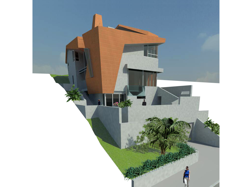 |
| Figure 17: Exterior view 1 |
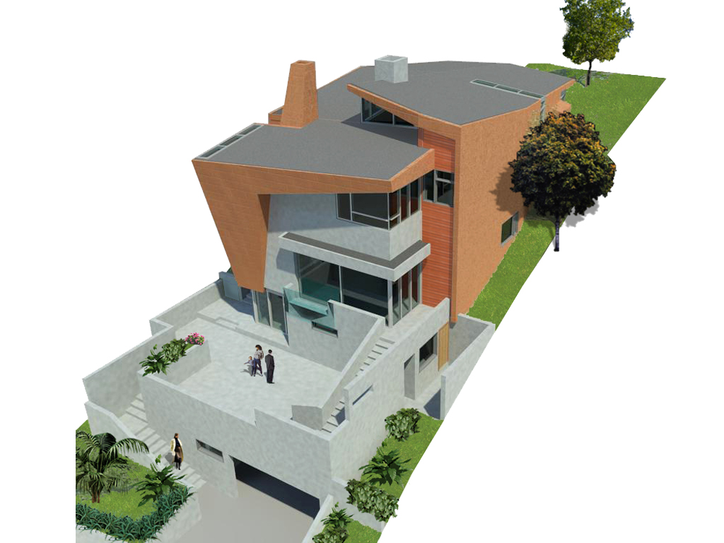 |
| Figure 18: Exterior view 2 |
 |
| Figure 19: Exterior view 3 |
 |
| Figure 20: Interior view 1 |
 |
| Figure 21: Interior view 2 |
 |
| Figure 22: Perspective Section |
The next post will be about Revit API, so stay tuned!
Very beautiful model of one of the most complex house designs produced by the Deconstructivists. It is great to see someone push Revit to the breaking point.
ReplyDeleteIf you were doing architecture like this in an office, would you model some of the more complex shapes in a 3D CAD system and import them into Revit?